What Are the Output Speeds and Directions of the Following Gear Trains
![]()
Illustration from Army Service Corps Training on Mechanical Transport, (1911), Fig. 112 Transmission of move and force past gear wheels, compound railroad train.
A gear train is a mechanical organisation formed by mounting gears on a frame and so the teeth of the gears appoint.
Gear teeth are designed to ensure the pitch circles of engaging gears ringlet on each other without slipping, providing a shine transmission of rotation from one gear to the next.[1] Features of gears and gear trains include:
- The gear ratio of the pitch circles of mating gears defines the speed ratio and the mechanical advantage of the gear set.
- A planetary gear train provides high gear reduction in a compact bundle.
- Information technology is possible to blueprint gear teeth for gears that are not-circular, nonetheless all the same transmit torque smoothly.
- The speed ratios of concatenation and belt drives are computed in the same way as gear ratios. See bicycle gearing.
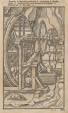
An Agricola illustration from 1580 showing a toothed wheel that engages a slotted cylinder to grade a gear train that transmits ability from a homo-powered treadmill to mining pump.
The transmission of rotation betwixt contacting toothed wheels can be traced back to the Antikythera mechanism of Hellenic republic and the s-pointing chariot of China. Illustrations past the Renaissance scientist Georgius Agricola evidence gear trains with cylindrical teeth. The implementation of the involute tooth yielded a standard gear design that provides a constant speed ratio.
Mechanical reward [edit]
Gear teeth are designed so the number of teeth on a gear is proportional to the radius of its pitch circle, and so the pitch circles of meshing gears roll on each other without slipping. The speed ratio for a pair of meshing gears can exist computed from ratio of the radii of the pitch circles and the ratio of the number of teeth on each gear.

Two meshing gears transmit rotational move.
The velocity v of the betoken of contact on the pitch circles is the same on both gears, and is given by

where input gear A with radius rA and angular velocity ωA meshes with output gear B with radius rB and angular velocity ωB . Therefore,

where NorthA is the number of teeth on the input gear and NB is the number of teeth on the output gear.
The mechanical advantage of a pair of meshing gears for which the input gear has NA teeth and the output gear has Due northB teeth is given past

This shows that if the output gear ChiliadB has more teeth than the input gear GA , and so the gear train amplifies the input torque. And, if the output gear has fewer teeth than the input gear, then the gear train reduces the input torque.
If the output gear of a gear train rotates more slowly than the input gear, and so the gear train is called a speed reducer. In this case, because the output gear must have more teeth than the input gear, the speed reducer amplifies the input torque.
Analysis using virtual work [edit]
For this assay, consider a gear train that has one degree of liberty, which ways the athwart rotation of all the gears in the gear train are defined by the bending of the input gear.
The size of the gears and the sequence in which they engage define the ratio of the angular velocity ωA of the input gear to the angular velocity ωB of the output gear, known as the speed ratio, or gear ratio, of the gear train. Let R be the speed ratio, then

The input torque TA acting on the input gear ChiliadA is transformed by the gear railroad train into the output torque TB exerted by the output gear GB . Assuming the gears are rigid and at that place are no losses in the engagement of the gear teeth, then the principle of virtual work can be used to clarify the static equilibrium of the gear railroad train.
Let the angle θ of the input gear be the generalized coordinate of the gear train, and then the speed ratio R of the gear train defines the angular velocity of the output gear in terms of the input gear:

The formula for the generalized force obtained from the principle of virtual work with applied torques yields:[2]

The mechanical advantage of the gear train is the ratio of the output torque TB to the input torque TA , and the to a higher place equation yields:

The speed ratio of a gear railroad train also defines its mechanical advantage. This shows that if the input gear rotates faster than the output gear, and so the gear railroad train amplifies the input torque. And if the input gear rotates slower than the output gear, the gear railroad train reduces the input torque.
Gear trains with two gears [edit]
The simplest case of a gear train has two gears. The "input gear" (also known as bulldoze gear) transmits ability to the "output gear" (also known as driven gear). The input gear will typically exist connected to a ability source, such as a motor or engine. In such an case, the output of torque and rotational speed from the output (driven) gear depend on the ratio of the dimensions of the two gears.
Formula [edit]
The teeth on gears are designed then the gears can coil on each other smoothly (without slipping or jamming). In lodge for two gears to ringlet on each other smoothly, they must exist designed so the velocity at the point of contact of the two pitch circles (represented by v) is the same for each gear.
Mathematically, if the input gear ThousandA has the radius rA and angular velocity , and meshes with output gear MB of radius rB and athwart velocity , then:


The number of teeth on a gear is proportional to the radius of its pitch circle, which means the ratios of the gears' angular velocities, radii, and number of teeth are equal. Where NA is the number of teeth on the input gear and NB is the number of teeth on the output gear, the following equation is formed:
This shows that a simple gear train with two gears has the gear ratio R given by:

This equation shows that if the number of teeth on the output gear YardB is larger than the number of teeth on the input gear GA , then the input gear GA must rotate faster than the output gear GB .
Double reduction gear [edit]

A double reduction gear comprises two pairs of gears, as single reductions, in series. In the diagram, the red and blue gears requite the first stage of reduction and the orange and light-green gears requite the second stage of reduction. The total reduction is the product of the get-go stage of reduction and the 2nd stage of reduction.
It is essential to take two coupled gears, of dissimilar sizes, on the intermediate layshaft. If a single intermediate gear was used, the overall ratio would be but that betwixt the commencement and final gears, the intermediate gear would simply act as an idler gear: it would reverse the direction of rotation, but non change the ratio.
Speed ratio [edit]
Gear teeth are distributed along the circumference of the pitch circle and then the thickness t of each tooth and the space between neighboring teeth are the aforementioned. The pitch p of the gear, which is the altitude betwixt equivalent points on neighboring teeth along the pitch circle, is equal to twice the thickness of a tooth,

The pitch of a gear ThouA tin can be computed from the number of teeth NA and the radius rA of its pitch circle

In society to mesh smoothly two gears ThouA and GB must have the same sized teeth and therefore they must have the same pitch p, which ways

This equation shows that the ratio of the circumference, the diameters and the radii of two meshing gears is equal to the ratio of their number of teeth,

The speed ratio of two gears rolling without slipping on their pitch circles is given past,

therefore
In other words, the gear ratio, or speed ratio, is inversely proportional to the radius of the pitch circle and the number of teeth of the input gear.
Torque ratio [edit]
A gear train can exist analyzed using the principle of virtual piece of work to show that its torque ratio, which is the ratio of its output torque to its input torque, is equal to the gear ratio, or speed ratio, of the gear train.
This means the input torque ΤA applied to the input gear GA and the output torque ΤB on the output gear GB are related past the ratio

where R is the gear ratio of the gear train.
The torque ratio of a gear train is also known as its mechanical advantage

Idler gears [edit]
In a sequence of gears chained together, the ratio depends merely on the number of teeth on the first and final gear. The intermediate gears, regardless of their size, do non alter the overall gear ratio of the chain. However, the improver of each intermediate gear reverses the direction of rotation of the last gear.
An intermediate gear which does not drive a shaft to perform any work is chosen an idler gear. Sometimes, a unmarried idler gear is used to reverse the management, in which case it may be referred to as a contrary idler. For case, the typical automobile transmission transmission engages reverse gear by means of inserting a reverse idler between 2 gears.
Idler gears tin also transmit rotation among distant shafts in situations where it would be impractical to simply make the distant gears larger to bring them together. Not simply do larger gears occupy more space, the mass and rotational inertia (moment of inertia) of a gear is proportional to the square of its radius. Instead of idler gears, a toothed belt or chain can be used to transmit torque over distance.
Formula [edit]
If a unproblematic gear train has iii gears, such that the input gear GA meshes with an intermediate gear GI which in turn meshes with the output gear GB , then the pitch circle of the intermediate gear rolls without slipping on both the pitch circles of the input and output gears. This yields the two relations

The speed ratio of this gear railroad train is obtained by multiplying these 2 equations to obtain
Notice that this gear ratio is exactly the same every bit for the case when the gears GA and 1000B engage directly. The intermediate gear provides spacing but does non impact the gear ratio. For this reason it is called an idler gear. The aforementioned gear ratio is obtained for a sequence of idler gears and hence an idler gear is used to provide the same direction to rotate the driver and driven gear. If the driver gear moves in the clockwise direction, then the driven gear also moves in the clockwise direction with the assistance of the idler gear.


Case [edit]

2 gears and an idler gear on a piece of farm equipment, with a ratio of 42/13 = 3.23:1
In the photo, assuming the smallest gear is connected to the motor, it is called the drive gear or input gear. The somewhat larger gear in the middle is called an idler gear. It is not connected directly to either the motor or the output shaft and only transmits power betwixt the input and output gears. There is a third gear in the upper-right corner of the photo. Assuming that gear is connected to the machine's output shaft, it is the output or driven gear.
The input gear in this gear train has 13 teeth and the idler gear has 21 teeth. Because only these gears, the gear ratio betwixt the idler and the input gear tin can be calculated as if the idler gear was the output gear. Therefore, the gear ratio is driven/drive = 21/xiii ≈1.62 or 1.62:1.
At this ratio, it means the bulldoze gear must make 1.62 revolutions to plough the driven gear once. Information technology also means that for every one revolution of the commuter, the driven gear has made ane/1.62, or 0.62, revolutions. Substantially, the larger gear turns slower.
The tertiary gear in the movie has 42 teeth. The gear ratio between the idler and third gear is thus 42/21, or 2:ane, and hence the terminal gear ratio is 1.62x2≈3.23. For every 3.23 revolutions of the smallest gear, the largest gear turns one revolution, or for every one revolution of the smallest gear, the largest gear turns 0.31 (1/three.23) revolution, a total reduction of about 1:3.23 (Gear Reduction Ratio (GRR) = 1/Gear Ratio (GR)).
Since the idler gear contacts directly both the smaller and the larger gear, it can be removed from the calculation, likewise giving a ratio of 42/13≈iii.23. The idler gear serves to make both the drive gear and the driven gear rotate in the same management, but confers no mechanical advantage.
Belt drives [edit]
Belts tin accept teeth in them as well and be coupled to gear-similar pulleys. Special gears called sprockets can be coupled together with chains, every bit on bicycles and some motorcycles. Once more, exact bookkeeping of teeth and revolutions tin can be applied with these machines.

For case, a belt with teeth, called the timing belt, is used in some internal combustion engines to synchronize the movement of the camshaft with that of the crankshaft, so that the valves open and close at the top of each cylinder at exactly the right fourth dimension relative to the movement of each piston. A concatenation, called a timing concatenation, is used on some automobiles for this purpose, while in others, the camshaft and crankshaft are coupled directly together through meshed gears. Regardless of which form of bulldoze is employed, the crankshaft-to-camshaft gear ratio is always ii:1 on four-stroke engines, which means that for every two revolutions of the crankshaft the camshaft volition rotate once.
Automotive applications [edit]
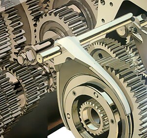
Analogy of gears of an automotive manual
Motorcar drivetrains more often than not take two or more major areas where gearing is used. Gearing is employed in the transmission, which contains a number of different sets of gears that tin can be changed to permit a wide range of vehicle speeds, and also in the differential, which contains the final bulldoze to provide further speed reduction at the wheels. In addition, the differential contains further gearing that splits torque equally between the two wheels while permitting them to accept different speeds when travelling in a curved path. The transmission and final drive might exist separate and connected past a driveshaft, or they might be combined into one unit called a transaxle. The gear ratios in transmission and final drive are important considering dissimilar gear ratios will change the characteristics of a vehicle'south performance.
Example [edit]
A 2004 Chevrolet Corvette C5 Z06 with a six-speed manual transmission has the post-obit gear ratios in the transmission:
| Gear | Ratio |
|---|---|
| 1st gear | 2.97:1 |
| 2nd gear | 2.07:1 |
| 3rd gear | 1.43:1 |
| 4th gear | 1.00:i |
| 5th gear | 0.84:1 |
| sixth gear | 0.56:i |
| opposite | −three.38:1 |
In 1st gear, the engine makes 2.97 revolutions for every revolution of the transmission's output. In quaternary gear, the gear ratio of 1:1 means that the engine and the manual's output rotate at the same speed, referred to as the "direct bulldoze" ratio. 5th and 6th gears are known equally overdrive gears, in which the output of the transmission is revolving faster than the engine's output.
The Corvette above has an axle ratio of 3.42:1, meaning that for every three.42 revolutions of the transmission's output, the wheels brand one revolution. The differential ratio multiplies with the manual ratio, so in 1st gear, the engine makes 10.16 revolutions for every revolution of the wheels.
The car's tires can almost be idea of as a third type of gearing. This car is equipped with 295/35-18 tires, which have a circumference of 82.1 inches. This means that for every complete revolution of the wheel, the car travels 82.1 inches (209 cm). If the Corvette had larger tires, it would travel farther with each revolution of the wheel, which would be similar a higher gear. If the motorcar had smaller tires, information technology would exist like a lower gear.
With the gear ratios of the transmission and differential and the size of the tires, it becomes possible to calculate the speed of the auto for a detail gear at a particular engine RPM.
For case, it is possible to determine the distance the machine will travel for one revolution of the engine past dividing the circumference of the tire by the combined gear ratio of the manual and differential.

It is likewise possible to determine a car'southward speed from the engine speed by multiplying the circumference of the tire past the engine speed and dividing past the combined gear ratio.

Note that the answer is in inches per minute, which can be converted to mph by dividing by 1056.[3]
| Gear | Altitude per engine revolution | Speed per 1000 RPM |
|---|---|---|
| 1st gear | 8.1 in (210 mm) | seven.7 mph (12.4 km/h) |
| second gear | xi.vi in (290 mm) | 11.0 mph (17.7 km/h) |
| 3rd gear | 16.viii in (430 mm) | 15.9 mph (25.6 km/h) |
| 4th gear | 24.0 in (610 mm) | 22.seven mph (36.5 km/h) |
| fifth gear | 28.6 in (730 mm) | 27.1 mph (43.6 km/h) |
| sixth gear | 42.9 in (ane,090 mm) | twoscore.six mph (65.3 km/h) |
Wide-ratio vs. shut-ratio transmission [edit]
A close-ratio manual is a transmission in which at that place is a relatively little difference between the gear ratios of the gears. For example, a transmission with an engine shaft to drive shaft ratio of 4:1 in showtime gear and 2:1 in second gear would exist considered wide-ratio when compared to another manual with a ratio of four:1 in first and iii:one in 2nd. This is because the close-ratio transmission has less of a progression between gears. For the wide-ratio transmission, the first gear ratio is 4:one or four, and in 2d gear it is 2:one or 2, and so the progression is equal to 4/2 = 2 (or 200%). For the shut-ratio transmission, beginning gear has a 4:1 ratio or 4, and second gear has a ratio of 3:ane or three, so the progression between gears is 4/three, or 133%. Since 133% is less than 200%, the manual with the smaller progression between gears is considered close-ratio. However, the departure between a shut-ratio and wide-ratio transmission is subjective and relative.[4]
Close-ratio transmissions are by and large offered in sports cars, sport bikes, and especially in race vehicles, where the engine is tuned for maximum power in a narrow range of operating speeds, and the commuter or rider can be expected to shift ofttimes to go along the engine in its power band.
Manufactory 4-speed or five-speed transmission ratios generally have a greater difference between gear ratios and tend to exist effective for ordinary driving and moderate performance utilise. Wider gaps between ratios let a higher 1st gear ratio for meliorate manners in traffic, just cause engine speed to decrease more when shifting. Narrowing the gaps will increase dispatch at speed, and potentially improve top speed under sure weather, but acceleration from a stopped position and performance in daily driving volition suffer.
Range is the torque multiplication difference between 1st and fourth gears; wider-ratio gear-sets have more, typically between 2.viii and iii.2. This is the single most of import determinant of depression-speed acceleration from stopped.
Progression is the reduction or decay in the pct drib in engine speed in the next gear, for example after shifting from 1st to 2nd gear. Most transmissions have some degree of progression in that the RPM drop on the 1-two shift is larger than the RPM drop on the 2-three shift, which is in turn larger than the RPM drop on the 3-4 shift. The progression may not be linear (continuously reduced) or washed in proportionate stages for various reasons, including a special need for a gear to reach a specific speed or RPM for passing, racing and so on, or simply economic necessity that the parts were bachelor.
Range and progression are not mutually exclusive, but each limits the number of options for the other. A wide range, which gives a stiff torque multiplication in 1st gear for excellent manners in low-speed traffic, specially with a smaller motor, heavy vehicle, or numerically low axle ratio such as 2.50, means the progression percentages must be high. The amount of engine speed, and therefore power, lost on each up-shift is greater than would be the example in a transmission with less range, only less power in 1st gear. A numerically low 1st gear, such as 2:1, reduces available torque in 1st gear, but allows more choices of progression.
In that location is no optimal choice of transmission gear ratios or a terminal drive ratio for best functioning at all speeds, as gear ratios are compromises, and not necessarily improve than the original ratios for certain purposes.
See besides [edit]
- Machine (mechanical)
- Machinery (engineering)
- Powertrain
- Wheel train (horology)
- Outline of machines
- Epicyclic gearing - related to turboprop reduction gear boxes
- Continuously variable manual (CVT)
- Virtual work
References [edit]
- ^ Uicker, J. J.; Thousand. R. Pennock; J. E. Shigley (2003). Theory of Machines and Mechanisms. New York: Oxford University Press.
- ^ Paul, B. (1979). Kinematics and Dynamics of Planar Machinery. Prentice Hall.
- ^ "Google: convert in/min to mph". Retrieved 2018-11-24 .
Formula: dissever the speed value past 1056
- ^ Cangialosi, Paul (2001). "TechZone Commodity: Wide and Close Gear Ratios". 5speeds.com. Medatronics. Archived from the original on 30 August 2012. Retrieved 28 Oct 2012.
External links [edit]
- Gear ratio at How Stuff Works
- Online Motorcycle gear train calculator at Gearingcommander.com
DOWNLOAD HERE
What Are the Output Speeds and Directions of the Following Gear Trains UPDATED
Posted by: cynthiamulend.blogspot.com
What Are the Output Speeds and Directions of the Following Gear Trains UPDATED. There are any What Are the Output Speeds and Directions of the Following Gear Trains UPDATED in here.

